Products
Technical Description
Design Brief
The kits provide a straightforward and accessible route to fitting compliant, sprung suspensions to proprietary OO (4mm scale) diesel locomotives as part of a conversion project to P4 or EM gauges. They use fold-up, etched brass, soldered construction coupled with simple steel spring wire suspension beams and require only soldering kit, hand tools and basic hobby metalworking skills to assemble.
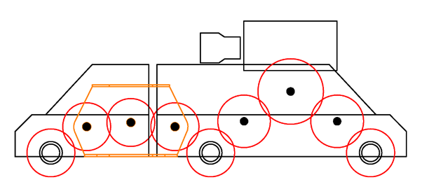
The articulation of six-wheeled drive units - a requirement for the sprung suspension - and the springing of unpowered axles in A1A-A1A or B1-1B configurations, as implemented by the kits, also provide reliable and complete solutions to the derailments sometimes experienced with six-wheeled bogies when simply converted to P4 or EM using ‘drop-in’ wheelsets.
Modification of the proprietary loco is kept to a minimum, the kits making use of the manufacturers' drive units and cosmetic bogie sideframes, together with standard wheelsets from the usual EM and P4 suppliers.
The kits make up into fully functional, unpowered, sprung bogies in their own right. Alternative detailing or mechanical parts could be used, depending on the nature of the project being undertaken.
Non-functional detailing parts are included where appropriate: for parts which are either missing from or placed incorrectly on the original mouldings, or to replace items, most usually brake rigging, that can not be retained when EM or P4 wheelsets are fitted.
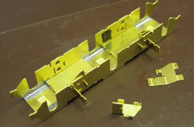
Principal Kit Components
The principal components to be made up from the kit for each bogie are:
a set of axle bearings,
an inside bogie subframe,
a bogie bolster.
These components are described in turn below.
Axle Bearings
To create each axle bearing, a turned brass Alan Gibson 4M65 2mm mainframe bearing is fixed in to an etched fold up carrier. The carriers are supplied, in groups, in fold-up jig frames. Assembly to the correct alignment is eased by the fold up jig around each group of carriers, which rests on the same flat surface as the back faces of the bearings.
The kits are designed for use with axles of 2mm diameter, though the bearings can be opened out to 3mm, or substituted by 1/8” (3.2mm) components, if needed.
The axle bearings slot into the bogie subframe…

Bogie Subframe
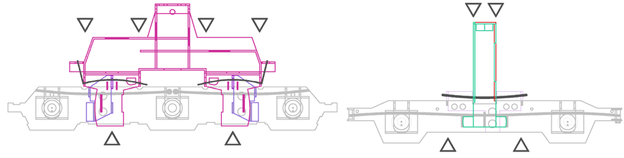
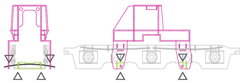
The bogie subframe is a rectangular 'U' shaped fold-up with upward facing slots to take the axle bearings. The bearings are aligned and retained in the subframe by the steel ‘guitar wire’ primary spring beams, which also transmit the weight of the loco from the subframe to the axles via the bearings.
In the six-wheeled bogies the primary springs are four independent simply-supported beams, arranged to provide a sprung-equalized suspension, analgous to the prototype.

In the four-wheeled bogies, the primary springs on each side are provided by a continuous single wire beam, which provides a degree of equalization between the two axles to simulate the equalization beam of the prototype.
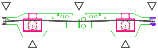
The primary springs have a static deflection, under the weight of the locomotive, of about 0.5mm.
The proprietary moulded cosmetic outer sideframe detail is attached to the bogie subframe, suitable fixing surfaces or mountings being provided by the kits. In some of the four-wheel designs, the sideframes slot in to the subframe transoms and retain the primary spring wires.
The subframe incorporates seatings for the secondary springs, which receive the weight of the loco from the bolster…

Bogie Bolster
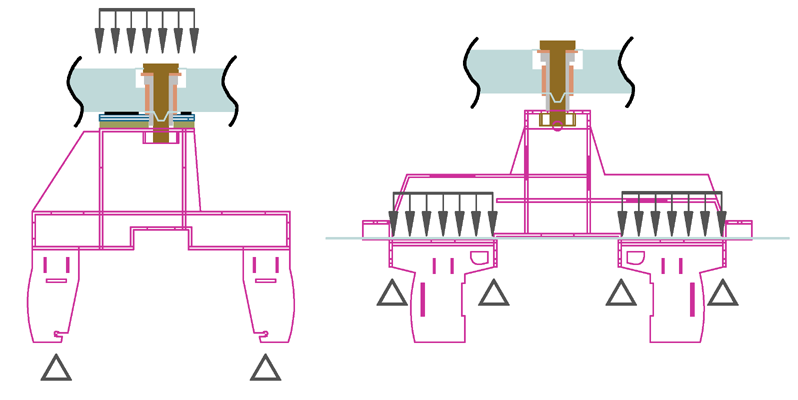
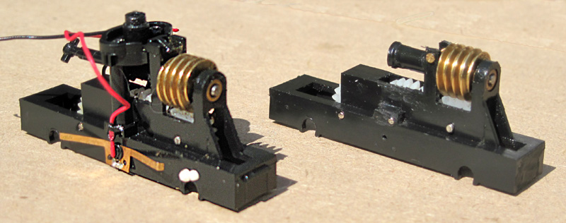
The bolster arches over the drive unit and is retained in the locomotive by its top pivot. It is supported on the bogie subframe by the simple beam guitar-wire springs which provide the secondary suspension. The springs also retain the subframe when the locomotive is lifted. They deflect 0.5 – 0.75mm under the weight of the loco.
For Heljan locos an etched fold up frame provides a pivot location to substitute for the original plastic ‘yoke’.
The bolster takes the weight of the locomotive via smooth plates, at either top-pivot or solebar level, in an arrangement which allows the bolster to rotate about the vertical axis through its top pivot (i.e. to provide steering movement) but prevents it either from rotating about the two horizontal axes (i.e. from ‘pitching’ and ‘rolling’), or from moving vertically, relative to the loco body. Those latter movements are accommodated in the secondary suspension, between the bolster and the subframe, and are controlled by the springs together with various interlocking and sliding surfaces. The overall result is that the effective transmission of tractive forces and weight, and the centres of pitch and roll rotations, occur low down within the bogie, as in the prototype.
Where appropriate, secondary spring hanger cosmetic detail is included on the bolster etch, and the moulded springs may be transferred from the proprietary sideframe moulding to the bolster, giving a greater depth of detail to the bogie.

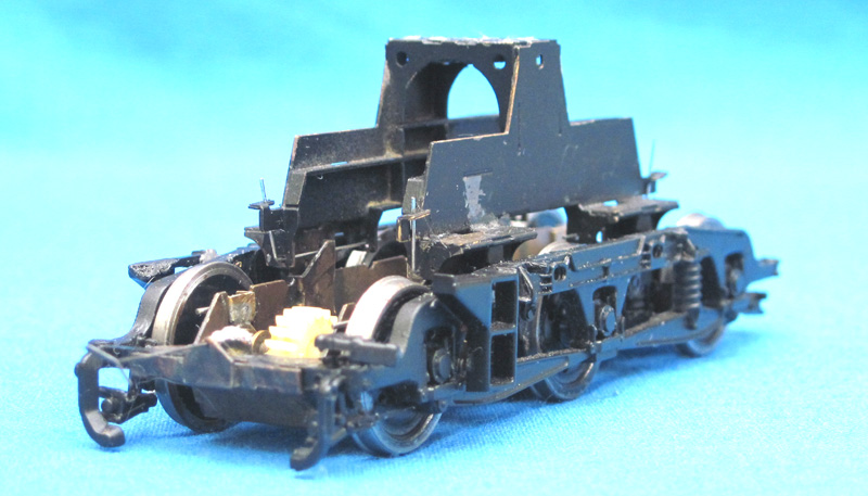
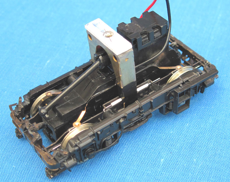
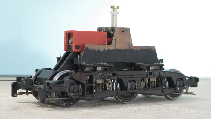
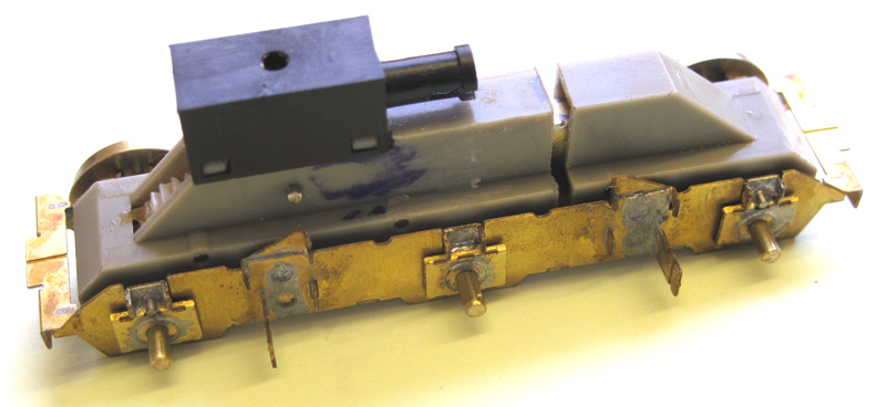
Drive Unit
The proprietary drive unit fits within the envelope of the subframe and bolster but is not in contact with either, being located solely by its original bearings on the axles. Pivot fixings and supports are removed from the drive unit and its axle bearings might need to be opened out fractionally to allow for relative movement of the axles in the suspension (though the existing tolerance is often sufficient).
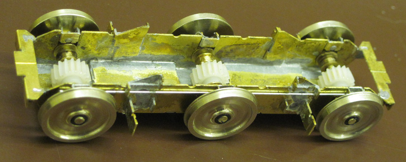
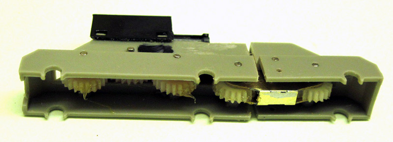
The Bachmann six–wheel drive unit is split between the middle and inner axles, an etched gear frame being provided to allow the drive to be articulated. Alternatively just the four-wheel part can be used. Equally, the bogie may be driven by four-wheel units such as those fitted to earlier 37s and 55s. Etched undertrays and end plates are fitted to the subframe to protect the exposed gears of the Bachmann drives.
The Heljan drives retain their plastic moulded undertrays and fit in to the subframes without major surgery. The A1A arrangement used by Heljan in their six-wheeled bogies provides ample pulling power.
The kits are designed for use with drive units having axles of 2mm diameter, though the axle bearings of the kit can be opened out to 3mm, or substituted by 1/8” (3.2mm) components, if needed.
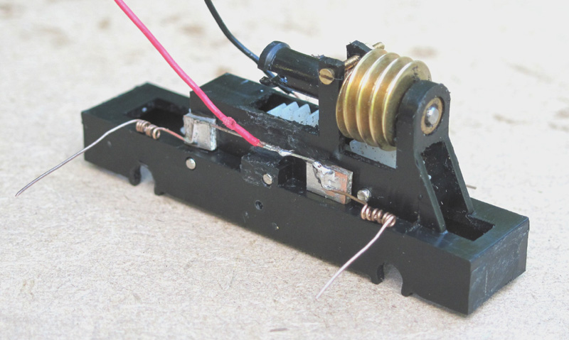
Pickups
Pickups are left to the preference of the builder. They are straightforward to arrange from fixings on the drive unit, as there is very little relative movement between the drive unit and the wheels.
Alternatively the ‘American’ system, where one bogie is ‘live’ at each polarity and the wheels on one side are either non-insulated or have their rims shorted to the axles, may be used to avoid pickups altogether. Insulating pivot components are supplied in the kits. Current can be collected from the pivot securing screw, so that there is no need to run any wires to the bogie itself.
Wheels and Axles
The kits do not include wheelsets. Axles of 2mm diameter are most suitable but, as noted in the ‘Axle Bearings’ section, other diameters can be used.
Wheels and axles from the following sources, among others, are advised when purchasing a new set for use with one of the kits:
Alan Gibson: Conversion Packs (all axles 2mm).
Branchlines: 14mm metal wheelsets. These are insulated on one side only, making them particularly useful for ‘American’ style electrical pickup (see above).
Ultrascale: Disc Diesel Wheels. Ultrascale ‘Conversion Packs’ generally need to be modified to remove portions of their inside wheel bosses and, in some cases, may have unpowered axles of other than 2mm diameter.