 Spring wire sizes are listed on the card inserts that come with the kits.
Spring wire sizes are listed on the card inserts that come with the kits.
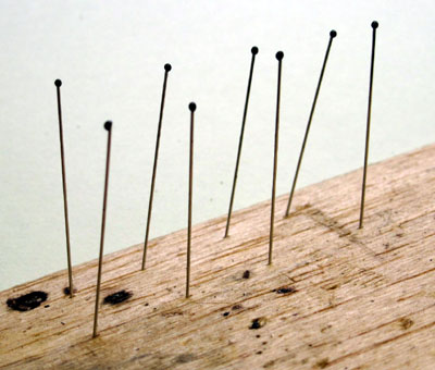
Cut eight lengths of the primary spring wire, each 32mm long.
Degrease the wires and apply, to one end of each wire, a bead of fast setting epoxy resin about 1mm diameter, i.e. just large enough to prevent the springs being pulled through the holes in the ears of the central bearing carriers. Put the springs to one side while the resin sets.
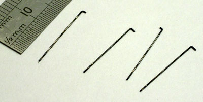 Cut eight lengths of the secondary spring wire, each 18mm long. At one end of each wire, make a 90° bend
1.5mm from the end.
Cut eight lengths of the secondary spring wire, each 18mm long. At one end of each wire, make a 90° bend
1.5mm from the end.
Return to the primary suspension wires and check that the epoxy resin beads have set.
 Take four of the primary springs, one of the central wheelsets, and
insert one through each of the
four holes in the ears of the bearing carriers, feeding them through until retained by the epoxy beads.
Take four of the primary springs, one of the central wheelsets, and
insert one through each of the
four holes in the ears of the bearing carriers, feeding them through until retained by the epoxy beads.
Check that the epoxy beads do not restrict the movement of the springs in the carrier. Reduce their length and/or diameter if necessary (having only recently hardened, they will respond quite well to paring with a sharp knife).
 Take the outer wheelsets, check their correct orientation to the central wheelset, and slide
their bearing carriers on to the primary springs.
Take the outer wheelsets, check their correct orientation to the central wheelset, and slide
their bearing carriers on to the primary springs.
 Find a block of material long enough to support the bogie subframe, deep and narrow enough to
allow the wheelsets to drop all the way down in their slots.
Find a block of material long enough to support the bogie subframe, deep and narrow enough to
allow the wheelsets to drop all the way down in their slots.
We use this tufnol jig for wheeling up and other assembly work. It allows the whole bogie to be turned round without disturbing any of the parts. The blocks to each side, between the wheels, were to help align sideframes, but can get in the way with other wheelbases.
 Place the bogie subframe on the jig. Pick up the three wheelsets together and rest them on
top of the subframe, with the bearing carriers of the central axles aligned over their slots.
Place the bogie subframe on the jig. Pick up the three wheelsets together and rest them on
top of the subframe, with the bearing carriers of the central axles aligned over their slots.
 Pull the primary springs outwards so that their inner ends are sitting properly in the tops
of the central bearing carriers.
Pull the primary springs outwards so that their inner ends are sitting properly in the tops
of the central bearing carriers.
Move the two outer wheelsets towards the ends of the bogie, until their bearing carriers are engaged in their slots. Adjust the assembly so that the primary springs are sitting on top of the secondary spring seats.
 Push the primary springs outwards and down over the secondary spring seats, until they are
resting on the tops of the primary spring seats.
Push the primary springs outwards and down over the secondary spring seats, until they are
resting on the tops of the primary spring seats.
 Using a small screwdriver, at one end of the bogie, push each primary spring outwards and downwards on to the outside
of its primary spring seat.
Using a small screwdriver, at one end of the bogie, push each primary spring outwards and downwards on to the outside
of its primary spring seat.
 Then push each spring further down until it clicks into place under its primary spring seat.
 Repeat for the two springs at the other end of the bogie.
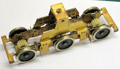
 You now have a rolling bogie with fully functioning equalized primary suspension. Do a
hand-powered rolling test to check for any tight bearings, wobbly wheels etc. It is easiest to correct
such things at this stage.
You now have a rolling bogie with fully functioning equalized primary suspension. Do a
hand-powered rolling test to check for any tight bearings, wobbly wheels etc. It is easiest to correct
such things at this stage.
 Fit the secondary springs to the subframes: insert the plain end of each spring through the secondary seat
adjacent to the spring retaining ear, then steer the plain end through the opposing seat, continuing to slide
the spring through the seats until the bent-over end slips inside the retaining ear.
Fit the secondary springs to the subframes: insert the plain end of each spring through the secondary seat
adjacent to the spring retaining ear, then steer the plain end through the opposing seat, continuing to slide
the spring through the seats until the bent-over end slips inside the retaining ear.
 Secondary spring after fitting.
 Now take the bolster, make sure it is the right way round,
and slide it into place over the subframe until the secondary spring seats of the bolster are resting
on the secondary springs. Using a small screwdriver, push each spring slightly inwards while pushing
the bolster gently downwards, so that the spring slides up the inner face of the seat and then snaps
into the slot in the seat.
Now take the bolster, make sure it is the right way round,
and slide it into place over the subframe until the secondary spring seats of the bolster are resting
on the secondary springs. Using a small screwdriver, push each spring slightly inwards while pushing
the bolster gently downwards, so that the spring slides up the inner face of the seat and then snaps
into the slot in the seat.
 Repeat the above operations for the other bogie so that you now have two rolling bogies.
 The bolsters are secured into the pivot frames using the M2 screws and nylon insulators provided in the
kit. A plastic card spacer is fixed to the top of the bolster, the thickness of the spacer being selected
to produce the desired ride height for the loco.
The bolsters are secured into the pivot frames using the M2 screws and nylon insulators provided in the
kit. A plastic card spacer is fixed to the top of the bolster, the thickness of the spacer being selected
to produce the desired ride height for the loco.
The nylon insulator is shortened so that the screw can clamp the pivot frame, spacer and bolster
up together without the insulator touching the top of the bolster.
The brass washer (8) can be omitted. It is useful as a soldering tag for the pickup wire if using
'American' current collection.
 On a piece of 60thou plastic card,
mark out two rectangles 8.5mm x 14mm. Find the centres of the
rectangles and make a 3mm diameter hole at each, to clear the main body of the nylon insulators.
Cut out the rectangles, and deburr their edges.
On a piece of 60thou plastic card,
mark out two rectangles 8.5mm x 14mm. Find the centres of the
rectangles and make a 3mm diameter hole at each, to clear the main body of the nylon insulators.
Cut out the rectangles, and deburr their edges.
 Shorten the nylon insulators so that, when inserted into the pivot frame, the unflanged part projects
below the base of the frame by less than the thickness of the plastic card spacer.
Shorten the nylon insulators so that, when inserted into the pivot frame, the unflanged part projects
below the base of the frame by less than the thickness of the plastic card spacer.
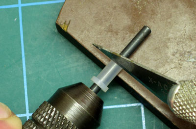
You can put the insulator over a 2 or 2.1mm drill, held in a pin chuck. This will prevent the insulator from collapsing while you roll it on the edge of a hard surface and make the cut with a sharp knife.
With the Pivot Frames fitted into the loco chassis block, fit the bogies - with their plastic spacers - into the frames, assembling the pivot components as shown in the diagram above. Swivel the bogies into position for straight track, and do up the M2 screws sufficiently to clamp the components fairly firmly together.
Place the loco onto a piece of straight, level track and check the ride height. If necessary, substitute different thicknesses of plastic card spacer until the desired height is achieved.
Ride height is normally set to give a nominal buffer height of around 13.8mm above rail level. You may well find that there is a variation in the order of 0.5mm over the four buffers, just in the way that they've been fitted to the loco. You might also wish to put the body back on to the loco and check for maximum height overall, and then reflect on whether the manufacturer has got the buffers in the right place. Ultimately, working to tenths of millimetres, it will be a judgement call as to exactly where the correct ride height lies.
Once you are satisfied with the spacers, glue them to the tops of the bolsters. Clamp them up against the pivot frames, using the M2 screws, while the glue sets.
Once the glue has set, mark the projecting threads of the pivot screws, remove and shorten them so they project no more than a thread's turn below the captive nuts.
Lightly coat the top of the bolster with silicone or multipurpose grease.
Refit the pivot screws and do them up until there is just a very light preload between the bolster top and pivot frame. You are aiming for a setting which allows the bogie to swivel freely, but prevents the bolster from rocking in the frame. You may well find that the screws slacken off as the bogies swivel: don't worry about that for now, in the final assembly they'll be retained by a thread locker.
You can now do static and rolling (pushed or pulled) tests to check ride height, body clearances, track-holding and suspension behaviour. It's helpful to clear any gremlins now, before the mechanical drives and detail are fitted. It is also extremely satisfying to feel how the locomotive moves with its sprung suspension.
Remove the bogies from the loco and dismantle them ready for the next stage: