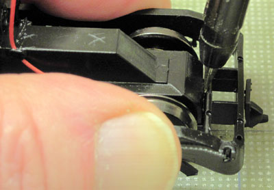
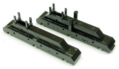
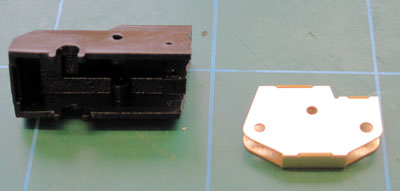
 Using a small screwdriver, gently unclip the bogie sideframe/undertray
moulding from the ends of the bogie drive unit.
Using a small screwdriver, gently unclip the bogie sideframe/undertray
moulding from the ends of the bogie drive unit.
This section describes the operations involved in modifying the drive units.
Following the manufacturers' recommendations for running-in, ensure that the locomotive is performing smoothly and to your satisfaction generally. Deal with any issues now, especially those covered by warranty or your basic statutory rights as customer, before making any modifications.
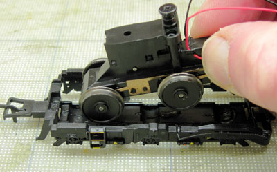
Separate the body moulding from the chassis block of the locomotive, according to the manufacturer's instructions. Store the body retaining screws safely away.
Make a note of the identification of the terminals on the circuit board to which the two wires leading to each bogie are connected. Note also to which side of each bogie they go. Pop off any insulated sleeves from the terminals and disconnect the wires leading to the bogies. It might be necessary to desolder them but they may just be passed through holes in the terminals and retained by the sleeves.
Select one of the bogies and undo the screw which retains the bogie pivot in the chassis block. Drop the bogie out from the bottom of the block. The cardan shaft joining the motor to the bogie will either come with the bogie or be retained at the motor end. Either way, remove it but note that the ears on each end of the cardan shaft are of subtly different shapes, so record which end is which.
Assign the bogie to one or other of your sets of etched bogie parts, marking the bogie drive and chassis block accordingly.
Similarly remove the other bogie.
Using a small screwdriver, gently unclip the bogie sideframe/undertray
moulding from the ends of the bogie drive unit.
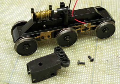
 Separate the Drive Unit from the Sideframe / Undertray and put the latter safely to one side for now.
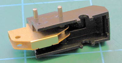
 Undo the two cross-headed screws retaining the bogie pivot / worm cover moulding to the tops of the two pivot
towers. Unclip the cover from the worm bearing support mouldings. Put the moulding safely to one side for now.
Undo the two cross-headed screws retaining the bogie pivot / worm cover moulding to the tops of the two pivot
towers. Unclip the cover from the worm bearing support mouldings. Put the moulding safely to one side for now.
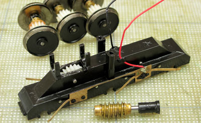 Unclip the three wheelsets from the drive train moulding and put them to one side.
Remove the worm with its shaft and bearings. Put them safely to one side.
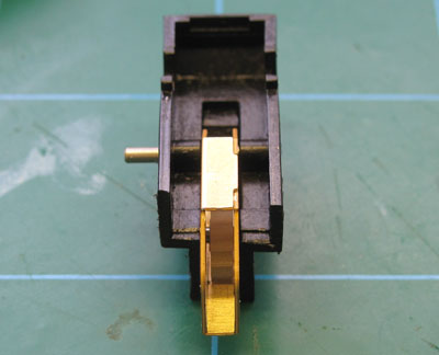
Undo the cross-headed screws which retain the metal pickup strips on the side of the drive train moulding. Remove the strips and, with a sharp knife, the moulded pips which locate them. Put the pickup wires, screws and strips to one side for reuse.
Rotate the three free idler gears, between the middle and inner axles, to feel how free running they are, as you will need to reproduce this later when reassembling the drive unit.
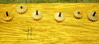 Gently press out the idler axles. We found that
the axles are a tight fit in one side of the moulding only so, once you have removed the first one and
thereby determined which side that is,
press them out from the tight side and, when the time comes, replace them from the loose side.
Gently press out the idler axles. We found that
the axles are a tight fit in one side of the moulding only so, once you have removed the first one and
thereby determined which side that is,
press them out from the tight side and, when the time comes, replace them from the loose side.
As you push out each axle, remove its gearwheel and note its position in the drive train so that you can replace it later in the same position. Note particularly that the central one of the three gears under the worm drive is of a different hand to the other two.
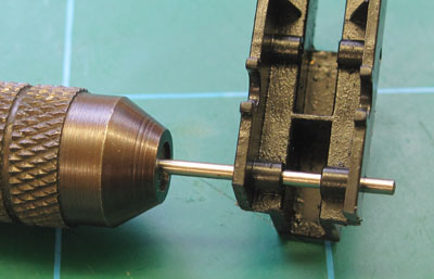
When removing the idler axles, support the moulding on a hard surface with some kind of slot or hole to receive the axle. We used the blind end of a 1.4mm drill, held in a pin chuck, to push the axles through.
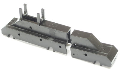
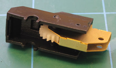
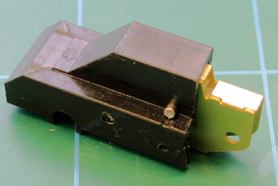
 Referring to the 'before' and 'after' illustration here, and
using your favoured combination of saws and craft knives or burrs, cutting discs and
grinders in a mini electric drill, cut down the drive train moulding as follows:
Referring to the 'before' and 'after' illustration here, and
using your favoured combination of saws and craft knives or burrs, cutting discs and
grinders in a mini electric drill, cut down the drive train moulding as follows:
Exercise some care as, in spite of being somewhat 'soft' and 'soapy', the plastic can crack in a brittle manner if overstressed. Take great care at all stages not to damage the retaining lugs for the main axle bearings.
 Cut the pivot parts from the combined Pivot / Worm Cover Mouldings.
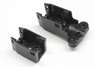
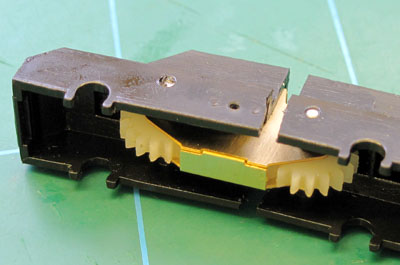
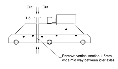 Split the Drive Unit between the inner two axles, by making
two cuts across the moulding between the idler axles, as shown here, about 1 to 1.5mm apart.
Split the Drive Unit between the inner two axles, by making
two cuts across the moulding between the idler axles, as shown here, about 1 to 1.5mm apart.
 A razor saw may be used to make these cuts. Take care that the moulding is adequately
supported while cutting - it's helpful to have a solid block of material which just fits between
the sides of the moulding.
A razor saw may be used to make these cuts. Take care that the moulding is adequately
supported while cutting - it's helpful to have a solid block of material which just fits between
the sides of the moulding.
 Give the drive unit assembly, including the idler axle holes, a thorough wash and degrease to remove all traces
of swarf and dust.
Give the drive unit assembly, including the idler axle holes, a thorough wash and degrease to remove all traces
of swarf and dust.
Refit the three idler gears and axles between the centre and outer axles, beneath the worm.
The kit is designed to allow the model to be driven on all six axles, i.e. as a C-C, corresponding to the Co-Co arrangement of the prototype. But you can avoid a certain amount of complication by using the 4-wheel parts of the drive as they are and assembling the loco as a B1-1B, in which configuration it will perform perfectly adequately and retain much of its hauling capacity. If you wish to take this option, you can skip the remaining steps in this section.
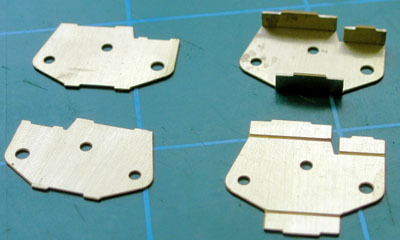 Remove the Drive Plate etches (D1, D2) from the fret. Check that the 1.5mm dia idler
axles are a free fit through the holes in the
plates (Note: one pair of holes is slightly larger than the others). Fold up the spacers on Plates D1.
Remove the Drive Plate etches (D1, D2) from the fret. Check that the 1.5mm dia idler
axles are a free fit through the holes in the
plates (Note: one pair of holes is slightly larger than the others). Fold up the spacers on Plates D1.
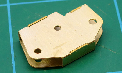 Fit the plates together as shown (there is no need to solder them together), making sure that the larger holes
are opposite each other, and that the assembly is square.
Fit the plates together as shown (there is no need to solder them together), making sure that the larger holes
are opposite each other, and that the assembly is square.
 Orientate each Drive Plate assembly with one of the smaller ends of the Drive Units.
 Slide the taller part of the Drive Plate assembly into the end of the Drive Unit and pin it in place with two of the idler axles.
Taking the three remaining idler gears, thin down their widths over bosses such that they are a free fit between the Drive Plates, a dimension of about 2.3mm. There may be a small moulding pip on the side of the gear which should be removed. Ensure that the thinned gears each rotate freely on the idler axles.
 The bosses of the plastic gears can be thinned by filing them down, and/or paring off with a very sharp knife.
To hold the gear while working it,
clamp one of the idler axles into a collet pin chuck with about 2.1mm projecting. The gear can then be placed
over the axle and worked with the file or knife while holding the pin chuck in the other hand.
The bosses of the plastic gears can be thinned by filing them down, and/or paring off with a very sharp knife.
To hold the gear while working it,
clamp one of the idler axles into a collet pin chuck with about 2.1mm projecting. The gear can then be placed
over the axle and worked with the file or knife while holding the pin chuck in the other hand.
Filing will leave 'fuzzy clods' of deconstituted plastic around both the outside edges of the bosses and the axle holes. It is essential that this waste is removed, using a sharp scalpel blade, as the smallest amount will cause the gears to run tight on the axles or bind against the Plates. Use the scalpel to put the tiniest of bevels around the circumference of the axle holes and outer edge of the bosses. Finish cleaning with a wash of methylated spirits scrubbed by an old toothbrush. Do not be tempted to relieve the axle holes with a broach or reamer - any tightness will be down to dust or swarf.
 Slide the
central (smaller) of the three idler gears into position between the plates, lining up with the
axle hole in the middle of the plates. Press the idler axle into place to retain the gear.
Slide the
central (smaller) of the three idler gears into position between the plates, lining up with the
axle hole in the middle of the plates. Press the idler axle into place to retain the gear.
 Similarly fit one of the other two gears and axles in the remaining idler axle position. Check
that the gears rotate freely.
Similarly fit one of the other two gears and axles in the remaining idler axle position. Check
that the gears rotate freely.
 Now slide the exposed end of the transmission plate assembly into the cut end of the
larger part of the Drive Unit moulding.
Now slide the exposed end of the transmission plate assembly into the cut end of the
larger part of the Drive Unit moulding.
 Slide the remaining idler gear between the Plates, line
it up with the holes in the plates, line up the holes in the plates with the holes in the
moulding, and insert the idler axle to retain the axle and plates in position. Check for freedom
of movement between the two parts of the drive train moulding: it should be sufficient for the inner
axle to move up and down about 1mm with respect to an imaginary line joining the centres of the other
two axles. It will probably be much more than this, but if there is a problem just file back the cut
edges of the moulding where they come close.
Slide the remaining idler gear between the Plates, line
it up with the holes in the plates, line up the holes in the plates with the holes in the
moulding, and insert the idler axle to retain the axle and plates in position. Check for freedom
of movement between the two parts of the drive train moulding: it should be sufficient for the inner
axle to move up and down about 1mm with respect to an imaginary line joining the centres of the other
two axles. It will probably be much more than this, but if there is a problem just file back the cut
edges of the moulding where they come close.
Check that the three idler gears rotate freely together as they did before disassembly. If any tightness is present, strip down the gears and ensure that they are clean and free from any kind of swarf or dust residues.
That concludes the modifications to the bogie drive units.