Bachmann Class 40: Wheelsets
 The diagram shows the arrangement of the driving wheelsets. Plain-ended axles of 2mm diameter are required:
pin-pointed ends should be removed.
The diagram shows the arrangement of the driving wheelsets. Plain-ended axles of 2mm diameter are required:
pin-pointed ends should be removed.
The kit is designed to use full-width solid steel axles with pickup on one side of each bogie via
uninsulated wheels on that side. This requires the Bachmann gear muffs to be opened out to fit the 2mm diameter
axles.
At least two wheels on one side of each bogie should be uninsulated.
Wheels from Alan Gibson or Ultrascale may be
'shorted out' (i.e. uninsulated) by various means, including those mentioned in the following paragraphs.
Branchlines 14mm coach wheelsets
(insulated on one side) may be used, as they come, for the driving wheels, though they are slightly under-sized.
Their similar 12mm
wheelsets may be used for the carrying wheels, though current stocks (as at November 2016) are insulated on both
sides.
 We have used this technique on Alan Gibson wheels. Make a curled end on a length of phosphor bronze wire and
solder it to the edge of one of the 2mm spacing washers supplied in the kit. Put a kink in the wire, shape it
so that the the washer sits flat against the wheel boss (for
the centre wheelset you might wish to thin the boss a little) and solder
it (very carefully) to the inside of the (pre-tinned) inner wheel rim (make sure it's not fouling the running part of
the rim). A slight misaligment will help
maintain electrical contact between the axle and the washer.
We have used this technique on Alan Gibson wheels. Make a curled end on a length of phosphor bronze wire and
solder it to the edge of one of the 2mm spacing washers supplied in the kit. Put a kink in the wire, shape it
so that the the washer sits flat against the wheel boss (for
the centre wheelset you might wish to thin the boss a little) and solder
it (very carefully) to the inside of the (pre-tinned) inner wheel rim (make sure it's not fouling the running part of
the rim). A slight misaligment will help
maintain electrical contact between the axle and the washer.
 Shorting Discs for Ultrascale wheels are available (to members only) from the Scalefour Society Stores,
www.scalefour.org, and are written up by their designer, Mark Humphrys,
in Model Railway Journal No. 248. We
have used these successfully and can recommend them. An alternative design is available from Brassmasters,
Ref A403 at www.brassmasters.co.uk/accessories.htm.
Shorting Discs for Ultrascale wheels are available (to members only) from the Scalefour Society Stores,
www.scalefour.org, and are written up by their designer, Mark Humphrys,
in Model Railway Journal No. 248. We
have used these successfully and can recommend them. An alternative design is available from Brassmasters,
Ref A403 at www.brassmasters.co.uk/accessories.htm.
The photo shows one of Mark's shorting discs fitted to an Alan Gibson wheel. It's not quite big enough to
reach the rim, even upside-down, so three short bridging lengths of PhB wire have been soldered in.
 A disadvantage of the solid disc is that the connection with the axle can be lost as the hole in the disc becomes a looser
fit on the axle as the wheels are removed and replaced. The flexibility of the Brassmasters type avoids that disadvantage
(as it can be distorted slightly to ensure that at least one edge is bearing firmly against the axle),
but the fixing to the wheel rim is more prone to failure. We have had some success with using thin shim of copper (from the
sheathing of satellite coax cable) soldered across the hole in the solid disc, to be punched through when the axle is fitted.
The shim can be replaced when necessary.
A disadvantage of the solid disc is that the connection with the axle can be lost as the hole in the disc becomes a looser
fit on the axle as the wheels are removed and replaced. The flexibility of the Brassmasters type avoids that disadvantage
(as it can be distorted slightly to ensure that at least one edge is bearing firmly against the axle),
but the fixing to the wheel rim is more prone to failure. We have had some success with using thin shim of copper (from the
sheathing of satellite coax cable) soldered across the hole in the solid disc, to be punched through when the axle is fitted.
The shim can be replaced when necessary.
In the following we refer to 'outer', 'centre' and 'inner' axles. On each bogie, the outer axle is that nearest
the coupling end. The inner axle is at the end of the bogie towards the middle of the loco, with the remaining
centre axle being the one in between. On the Bearing Carriers (C1) and Subframe Mainframes (S4) the inner axles
are indicated by a single half-etched dot, the outer axles by two half-etched dots (see the
Bearing Carriers
instructions for a full explanation of the marking system).
Dismantle the Bachmann OO wheelsets. Recover the final drive gear muffs and the axle bearings, noting, on the
four inner and outer axles, that the bearings have two grooves, the outer, narrower of which engaged with
the brass pickup strips.
Discard the wheels and axles.
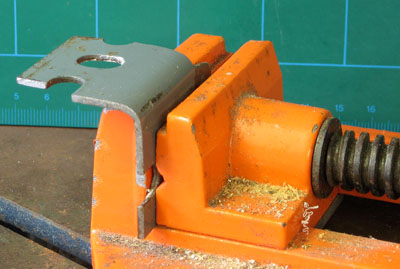 To ease the wheelsets apart without undue distortion of the central plastic gear muffs,
an old piece of Dexion angle, clamped into a vice, serves in our workshop as a reaction frame…
To ease the wheelsets apart without undue distortion of the central plastic gear muffs,
an old piece of Dexion angle, clamped into a vice, serves in our workshop as a reaction frame…
 …with the back of one of the wheels up held against the angle, and the tapered jaws of
a small pair of pliers, held closed around the hub and resting on the underside of the gear, used to lever
the muff axially away from the stub-axle…
…with the back of one of the wheels up held against the angle, and the tapered jaws of
a small pair of pliers, held closed around the hub and resting on the underside of the gear, used to lever
the muff axially away from the stub-axle…
 …the same repeated for the wheel/stub-axle on the other side of the gear muff.
Open out the bore of each of the plastic gear muffs to fit your 2mm replacement axles. The fit should be
sufficiently tight to prevent slipping under load, but not so tight as to be in danger of splitting the plastic.
The bores of the plastic gear muffs may be opened out by drilling through the bore, being careful to maintain
its axial trueness. We start with a 1.6mm drill, and increase drill size in small (0.1mm)
increments up to 2.0mm. The increments you use may depend on what drills you have to hand and what are their
exact diameters (measured over the cutting flutes).
Other parties have reported successfully carrying out this operation entirely by hand,
holding the drills in a pin vice and the gear muff in a larger
chuck. We have used a lathe, turned by hand rather than using the motor. Care is needed to chuck the gear
muff firmly enough to retain alignment and not slip, yet not so tight as to cause it to distort.
Experience suggests that a final pass with a 2.0mm drill will give a
suitable fit. It is possible that the flexible plastic shrinks back a little after the cut.
The exact size of the drill and the exact axle diameter could be significant (our '2mm'
drill mikes up at 1.98mm. Imperial drill sizes No 48, 47 and 5/64" all lie within the range 1.9 - 2.0mm).
If you do end up with a fit which is insufficiently tight, Loctite could be a solution, perhaps
with a groove machined in the axle to give space and a key for the adhesive.
 Press the gear muffs on to the 2mm driving axles, centreing them in position.
 Take the eight inner and outer Bachmann axle bearings, and remove the pickup flange and groove from each. Note that the
remaining grooves are not as wide as those on the bearings for the centre axles.
Take the eight inner and outer Bachmann axle bearings, and remove the pickup flange and groove from each. Note that the
remaining grooves are not as wide as those on the bearings for the centre axles.
The grooves and flanges can be filed away by placing the bearing over the end of one of the OO stub axles held
in a pin chuck, and working the bearing against the face of a file, using the pin chuck and axle as a holder.
The Bachmann axle bearings need to be opened out to accommodate differential
movements of the axles in the suspension whilst at the same time holding the drive gears in mesh and
transmitting the tractive forces from the drive train to the axles.
Open out the internal diameter of each of the Bachmann 2mm axle bearings to about 2.2mm.
We found that the tapered end of a 2.3mm cutting broach was about 2.1mm diameter so
used that to cut half way through the bearing from each side, finishing off with a smooth broach.
Not a technique for the purist, perhaps, but adequate for our purpose. Alternatively, using a lathe,
we have simply drilled through the bearings.
 Allocate pairs of the Bachmann axle bearings to pairs of the kit's Bearing Carriers: the wider, centre bearings
to the centre carriers (no axle id dots), the narrower inner/outer axle bearings to the carriers for the outer axles
(two dots), and the inner axle (one dot).
Allocate pairs of the Bachmann axle bearings to pairs of the kit's Bearing Carriers: the wider, centre bearings
to the centre carriers (no axle id dots), the narrower inner/outer axle bearings to the carriers for the outer axles
(two dots), and the inner axle (one dot).
The following operations check the differential movement between the drive train
and the bogie subframe. Repeat them for each bogie in turn.
Collect together the Drive Unit, brass bogie Subframe, Bearing Carriers, axles and Bachmann axle bearings
for the bogie.
 Taking the axles one at a time, slide on to each axle the Bachmann axle bearings followed by the
kit's Bearing Carriers. Note that the ears at the tops of the bearing carriers face outwards
towards the ends of the axle.
Taking the axles one at a time, slide on to each axle the Bachmann axle bearings followed by the
kit's Bearing Carriers. Note that the ears at the tops of the bearing carriers face outwards
towards the ends of the axle.
 Take the centre and outer axles and clip them in to the Drive Unit using the Bachmann bearings.
Check for sufficient differential twisting movement between the two axles: view the drive unit end-on, and
the axle ends should be free to move up and down about ±0.5mm with respect to one another when the axles are
twisted in opposite senses about the longitudinal axis of the unit.
Orientate the Subframe and the Bachmann drive unit. The 'four-wheeled'
part of the drive unit goes towards the outer (i.e. pony truck) end of the bogie, driving the centre and
outer axles, with the socket for the cardan shaft facing the inner end of the bogie. Fit the drive unit
into the Subframe, engaging the four bearing carriers into the slots in the
subframe.
 Holding the Drive Unit with one hand and the Subframe with the other, check that the Drive Unit
can move freely up and down relative to the Subframe with the carriers sliding in their slots. At rest
the tops of the
carriers will be level with the tops of the subframes. The suspension is designed to deflect
±0.5mm, so the free movement needs to be maintained both when the base of the drive unit is parallel
with the base of the subframe, and when one axle is raised up to 1mm with respect to the other.
If there is any binding when the units are parallel, check the movement of individual carriers in their
slots and correct as necessary. If there is binding when one axle is raised, open out the Bachmann axle
bearings just a fraction more, up to a maximum of 2.3mm.
Holding the Drive Unit with one hand and the Subframe with the other, check that the Drive Unit
can move freely up and down relative to the Subframe with the carriers sliding in their slots. At rest
the tops of the
carriers will be level with the tops of the subframes. The suspension is designed to deflect
±0.5mm, so the free movement needs to be maintained both when the base of the drive unit is parallel
with the base of the subframe, and when one axle is raised up to 1mm with respect to the other.
If there is any binding when the units are parallel, check the movement of individual carriers in their
slots and correct as necessary. If there is binding when one axle is raised, open out the Bachmann axle
bearings just a fraction more, up to a maximum of 2.3mm.
 If you are having three driven axles, remove the drive unit from the subframe and clip
the third, inner, axle into place. Replace the drive unit in the subframe, now engaging all six of the bearing
carriers into their slots. Holding the 'four-wheeled' part of the drive unit such that the tops of all four of its
bearing carriers are level with the top of the subframe sides, check that the third axle has at least
±0.5mm
of vertical travel. If this is not the case, check for free movement of the individual carriers in their
slots and then, if required, open out the Bachmann bearings a little more, on this axle only,
up to a maximum of 2.3mm.
If you are having three driven axles, remove the drive unit from the subframe and clip
the third, inner, axle into place. Replace the drive unit in the subframe, now engaging all six of the bearing
carriers into their slots. Holding the 'four-wheeled' part of the drive unit such that the tops of all four of its
bearing carriers are level with the top of the subframe sides, check that the third axle has at least
±0.5mm
of vertical travel. If this is not the case, check for free movement of the individual carriers in their
slots and then, if required, open out the Bachmann bearings a little more, on this axle only,
up to a maximum of 2.3mm.
That concludes the test. Unclip the axles from the Drive Unit and
put them to one side, ensuring that each axle bearing is kept with its respective Bearing Carrier.
Pair off each driving wheel with one of the bearing carriers, with the non-insulated wheels allocated to the
same side of each bogie (corresponding to the side of the Bogie Bolsters to which you have fitted the pickup
strips).
We now assemble one of the outer wheelsets to check for lateral play.
Take the wheels, Bearing Carriers and axle bearings for one of the 'two dot' outer axles and assemble them on
to the axles to the correct back-to-back measurement.
Test fit the axle in its slot in its bogie subframe to determine the amount of lateral play.
There should be just enough to allow the wheelset to tilt such that the
wheel on one side is raised about 1mm with respect to that on the other. If necessary,
dismantle the wheelset and fit full- and half-thickness
2mm washers (supplied on the fret) between the bearing carriers and wheels, until this condition is met.
If there is insufficient play, even with no washers
fitted, reduce the inner width of the wheel bosses accordingly.
Record the washer configuration you arrived at. If
you had to reduce the inner wheel bosses, repeat the operation on the remaining wheels. Take off
an extra 0.5mm on the wheels for the two centre axles, subject to not going beyond the line of
the inner wheel rim.
Now we can assemble the remaining wheelsets.
Assemble the inner wheelset, inserting washers as for the outer wheelset.
Assemble the centre wheelset. This wheelset will have no, or fewer, washers, to allow sideplay. In P4, with
gauge widening, ±0.5mm is enough, ±0.75mm plenty.
Test fit each inner and outer axle in its slot to confirm that they have the correct number of spacing washers.
The fit should be sufficiently loose to allow the axles to spin freely, and
the bearings should move freely up and down in the slots.
Lubricate the bearings with a light machine oil and ensure that the oil is taken in to
all the axle-bearing interfaces.
It just remains now to fit the wheelsets to the Pony Truck etches.
 Check that the axles are a free running fit in the Pony Truck bearings.
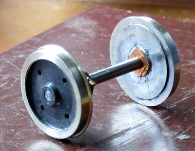
 If you start with pin-point axles
like those above, you can turn down the ends to represent the cylindrical extensions that the prototype has.
If you start with pin-point axles
like those above, you can turn down the ends to represent the cylindrical extensions that the prototype has.
 Fit one of the axles to one of the Pony Trucks, and fit the wheels to the correct back-to-back (and to the
correct sides, if one of them is uninsulated). Fit 2mm
washers inside the wheels, if required, to take up any lateral slack, but leave enough to keep the wheelset
a free-running fit.
Fit one of the axles to one of the Pony Trucks, and fit the wheels to the correct back-to-back (and to the
correct sides, if one of them is uninsulated). Fit 2mm
washers inside the wheels, if required, to take up any lateral slack, but leave enough to keep the wheelset
a free-running fit.
Similarly, fit the remaining wheelset to the other Pony Truck.
That completes the assembly of the wheelsets.